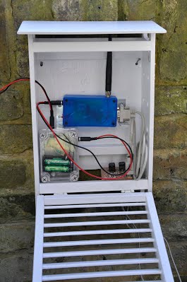
 This is a far cheaper and simpler setup than the first prototype. The RFu328 draws just over 30 milliamps (about a third of the original XinoXF) which makes the solar power setup easier. I've also split off the sensors from the Arduino. The original XinoXF and SparkFun Weathershield version left the XinoXF (that's an Arduino clone with a built in transmitter by the way) far too exposed. To facilitate that split, I made a sensor board out of a spare piece of Veroboard, some SparkFun sensors (BMP180 for pressure and HTU21D for humidity and temperature) and RJ11 sockets for my rain/wind sensors plug into. By the way the SparkFun stuff is available in the UK from the admirable ProtoPic. To hook the sensors to the RFu328 I used a old-style RS232 serial cable so I had a pluggable, modular solution. The eventual end-game will be to produce a proper PCB for the sensors and RJ11 sockets. Meanwhile the inside of the Stevenson screen (right) looks moderately tidy! Along the way I have had to do a bit of recoding on the Arduino end and even learned how to make and calibrate a voltage splitter to measure the wind direction. Next steps
The photos below show the inside of the transmitter with the RFu328 at its heart. Next are two pics of the sensor board showing the RS232 cable connected. Finally there is the box holding the AA batteries and the LM317T charge controller. The solar panel plugs in the left side, the cable to the transmitter plugs into the top. 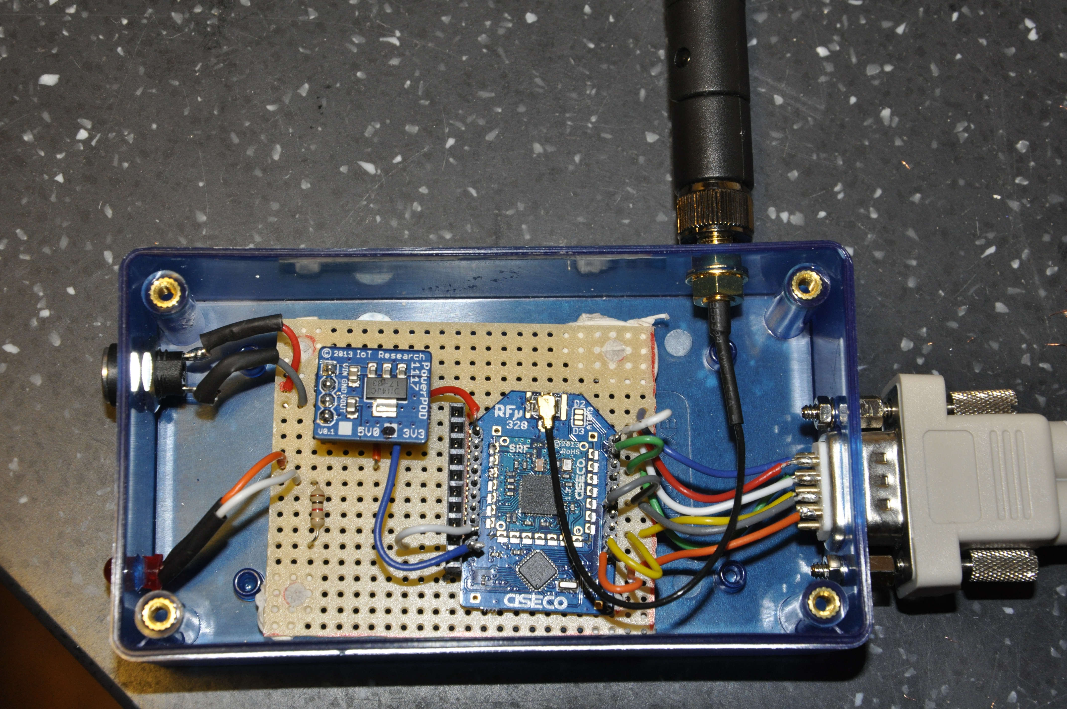 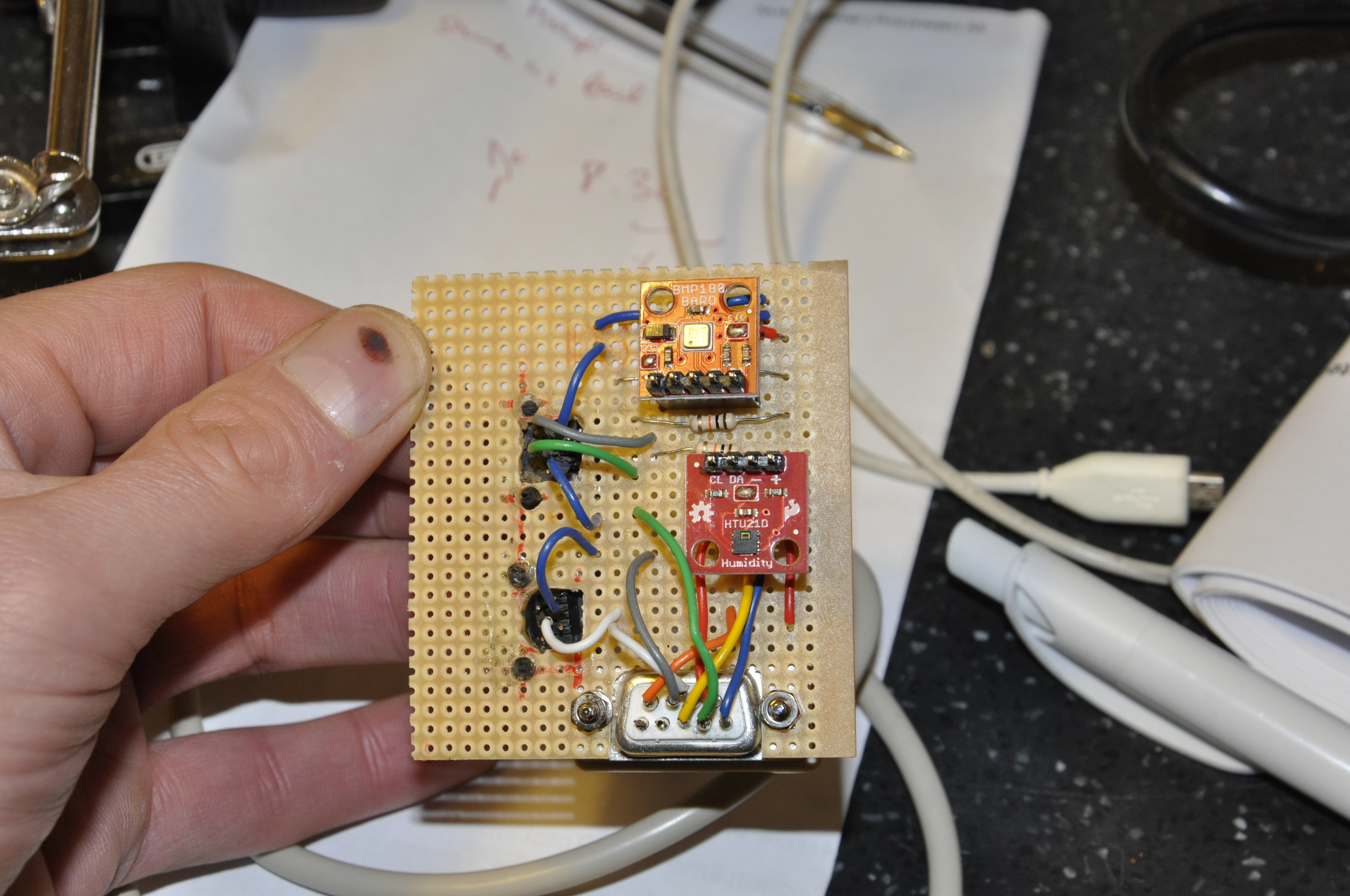 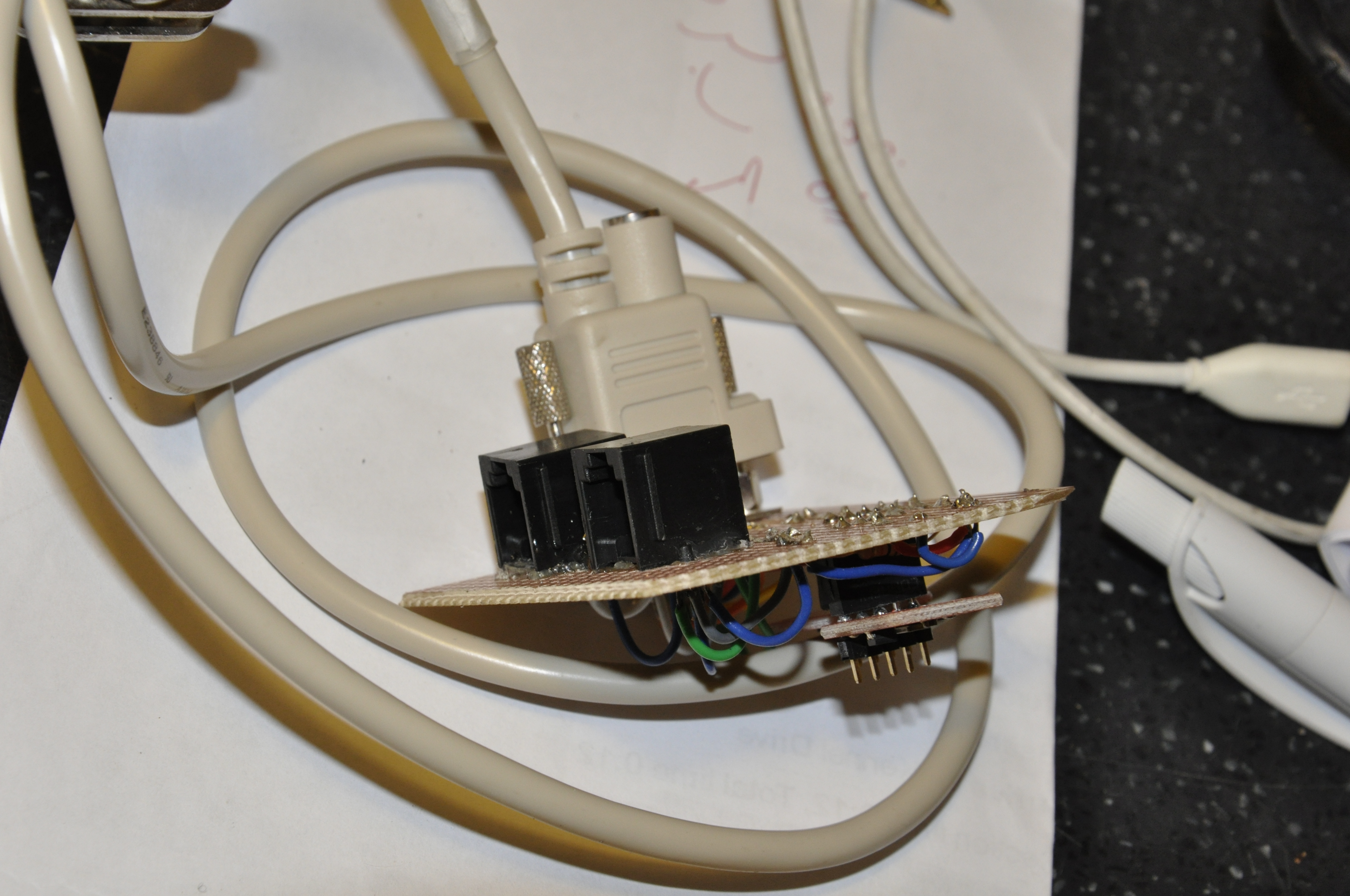 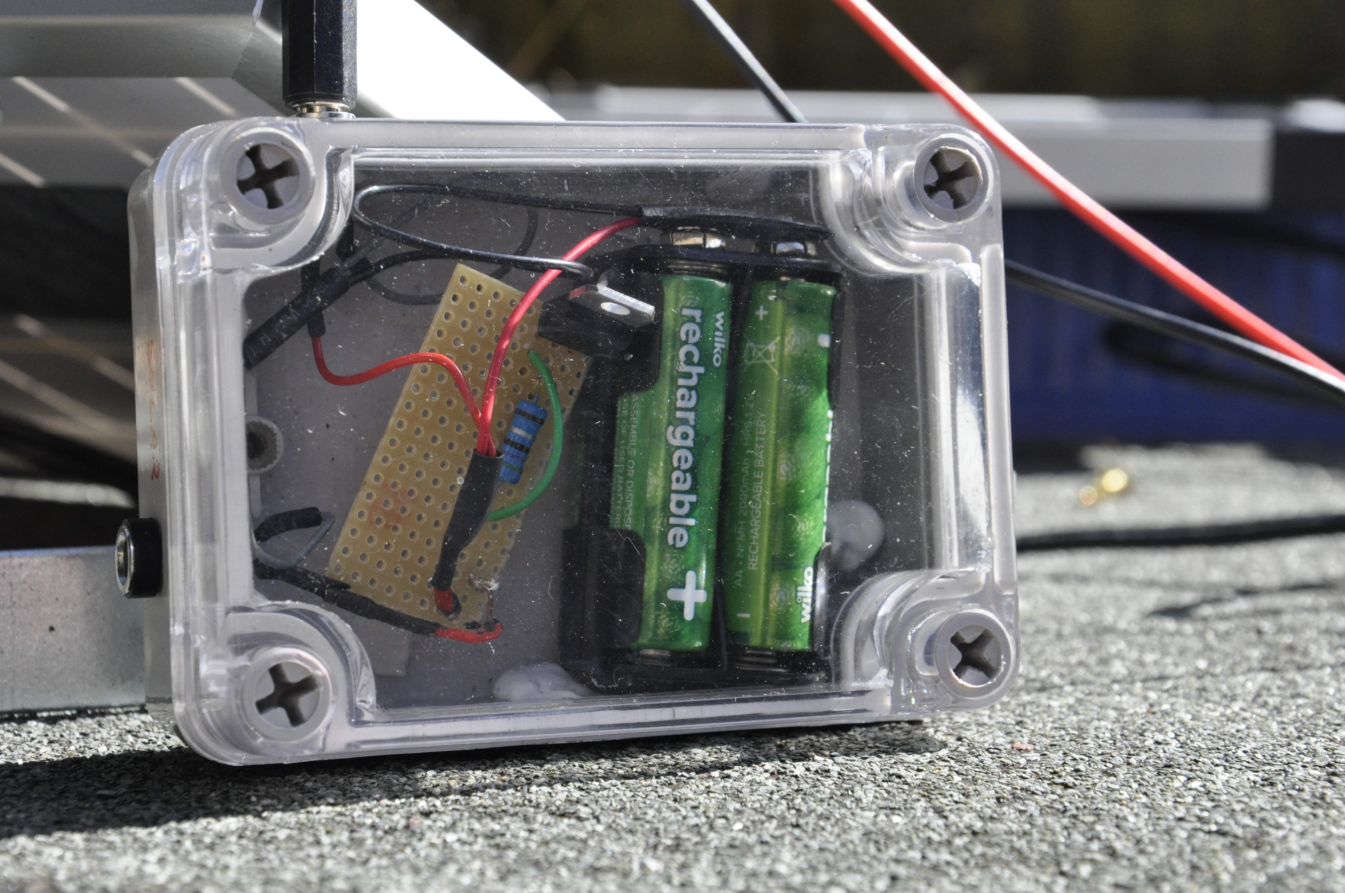 |
Pi Blog >